
Designed by Eng. João Roberto Gabbardo, Ms.C,
Introduction
Some time ago I developed a circuit to help all CP growers on the cumbersome task of fill the water trays were the pots stand. All of us know the problem about how fill the trays when we want go to a vacations trip. Normally one ask to parent, neighbor or friend to do the task and gone to the vacations. But frequently we think on how the plants are going and the vacation can be turned on a nightmare. When we return we have normally a surprise – but the bad one! The very difficult to grow Drosophyllum Lusitanicum or the most beautiful Heliamphora is on a very poor state or worst: the plant died! Because I have had a similar problem I projected and built a circuit capable of monitor the water level and fill automatically the trays. The circuit was thought to be simple and cheap, but most growers didn’t had skills on electronics and never encourage yourself to assemble it. So I thought on an all mechanical sprinkler system using ordinary buoy valve types, again taking on mind the low coast and the easy assembling.
Well let’s stop to talk about the advantages and go to the assembly.
What you will need
Some buoy valve types, the cheap ones used on toilets water tanks or regular water tanks. The first is the better because the small size, but the choice will depend of the size of the trays used. Also you will need some hose, hose clamps, proper hose terminals and some plumbing hardware like knees, nipples, T type junctions and Teflon tape to prevent water leakage on the plumbing connections. See the Photo 1:

Photo 1: Basic material to the sprinkler system
Of course the material can vary slightly according to the grower conditions i.e. type and
number of trays and the available material on local hardware suppliers.
How it works
The heart of the system is the buoy valves type; these valves have a small hole where the water flow and a piston covered with some kind of soft material like rubber on one edge to lock the hole to stop the water flow. The piston is connected to an arm, normally a short metal tube fixed on the buoy. The valve is normally attached on the wall of toilet water tanks or regular water tanks but here the valve will be fixed on the trays. The buoy/arm moves up and down and the piston moves horizontally closing or opening the hole. Please refer to Figures 1 and 2 (not in scale) showing the described. On the Figure 1, the water level forces the buoy/arm upward and the piston to the left closing the hole. Figure 2 show the buoy/arm downward with the water level decreased, so the piston moved to the right opening the hole.
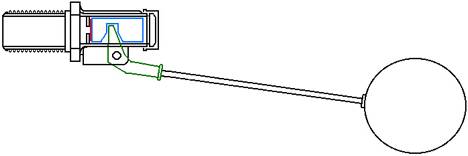
Figure 1: Valve closed

Figure 2: Valve opened
Now the water will flow filling the tray and the buoy/arm raise making the piston moves horizontally until close the hole and stopping the water flow. The water level can be adjusted by the user simply folding the valve arm.
The Photo 1 show the valve used on the present system disassembled.

Photo 1: Valve disassembled
Top: the buoy and arm. Bottom from left to right: the locking nut, valve body, piston, pin that fix the arm on the valve body, cap of the body.
Assembling the system
The first step to do is drill the holes on the trays to attach the valves. Put the buoy inside the tray, near the inner side wall. Let a space of 1cm (0.39 in) from the inner wall to the buoy allowing a free movement to the buoy. Mark the position on the tray border. Now use the inner side of the plastic nut of the valve as gauge pattern to the hole, marking a circle on the outside (Photo 2) of the tray wall. Make the circle nearest the upper edge to allow a wide up/down movement to the buoy.
Drill a small hole on the center of the marked circle and enlarge it using a round file until the valve could be firmly attached. Look the Photo 3, the hole was drilled as described. Doing so it will make an easily water level adjust after the valve was attached to the tray. What I’m saying it? Handle the valve and you will see that the piston of the valve has a small course. The photo 4 show the small gap with the valve completely opened.

Photo 2: Positioning the buoy
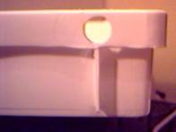
Photo 3: Big hole on the tray

Photo 4: Valve opened
If the tray is too flat the adjustment can be some difficult to do, so attempt to not use flat ones!
Should be a good idea drill some drainage holes on the tray, if the valve do not lock the water will fill entirely the tray flooding the pots. Look the Photo 5. The 2 holes were drilled at height of 3 cm (1.18 in) from the bottom of the tray.
Now insert the valve, lock the nut and cover the exposed treads with some layers of Teflon tape to prevent any water leakage (Photo 6). If the trays were located near a wall the hoses can be crunched. To overcome this problem you should use some additional plumbing. One knee with the same inner gauge of the valve screw and a nipple will do the job (Photo 7 and 8). Do not forget cover the treads with Teflon tape before attach the pieces!

Photo 6: Valve locked

Photo 5: Drainage holes

Photo 7: Knee and nip

Photo 8: Hose attached
The hose run parallel to the tray and never will be crunched by the house wall. The tray showed on the photos has the following dimensions: 68 cm (26.77 in) length, 36 cm (14.17 in) width and 9 cm (3.54 in) depth. The maximum water level was adjusted just below the drainage holes by folding the buoy arm as showed on the photos.
Now is time to lead the water to the trays. The easiest way is make use of ordinary garden’s hose. You can run the hose form the tank or tap (if possible) to the trays. You will need some T junctions for hoses, knees and nipples to distribute the water to all trays. Photo 9 shows an example of how you can do it. Here 2 T junctions were locked together using a nipple to distribute the water to 3 trays. All hoses were locked using hose clamps to avoid water leakage. The Photo 10 and the following show the valves installed and the system working properly.

Photo 9: Water distribution

Photo 10: Valve installed and working

Photo 11: Valve installed and working

Photo 12: Valve installed and working

Photo 13: Valve installed and working

Photo 14: Hoses installed
Improvements
This first version made use of three valves, one on each tray to allow a estimation of the system performance and to allow future expansions, but use one buoy on each tray is not advantageous at first insight because the buoy and arm rob a big space inside the tray, it could be used to accommodate some pots. Another approach can be used if all trays are on the same height: make use of a single valve on one of the trays or use a separate small box or tray where the buoy/arm should be fit inside. The box or tray must be placed on the same level of the trays and the communicating vessels should be employed. How do it? It is very easy; you will need some more plumbing hardware like nipples, plastic nuts (PVC type) to fix the nipples on the trays, hose terminals, hose clamps and some hose.
How does it
Like described later, make use of the nut as gauge to drill the holes, but instead later the holes should drilled as near the bottom possible. Mark the circle on the outside wall of the box or tray, drill one small hole on the center of the circle and enlarge it using a round file until the nipple could be firmly inserted. Fix the nipple using the nut. Repeat the procedure to the other trays except for the last tray. Cut some pieces of hose sufficiently long to connect the trays, insert the hose terminals and fix using the hose clamps. Attach the hoses and the system is ready to use.
How it works? The communicating vessels behave on an interesting way. If we place some recipients with different heights and diameters that can be filled with water and they communicate (preferably near the bottom) so the water can flow from one to other. If we put some water on one recipient, the water will flow to the other recipients (by the communications) until the water level be the same on all of them. If we put some more water, again the water level will raise to the same level on all recipients. Remember, the box or tray with the buoy is connected to all trays, so the water level on all trays will be the same there.
Another improvement on the system can be made using the “quickly clamp” garden hardware. The “quickly clamp” connectors allow fast and easy disassemble/assembly of the system to clean the trays. On the other hand, this hardware is more expensive than ordinary plumbing hardware and is quickly damaged when exposed to the sunlight for long periods of time because the UV rays.
Possible problems
The system is very simply, so some possible problems can be predicted. The system is entirely mechanical and has moving parts, so these parts will worm. But it will be very difficult perhaps impossible get spare parts to the valves; in that case the valve shall be substituted. Sometimes the valve can lock because the dirty accumulated on the arm fixation pin. You will need remove the valve, disassemble and clean it using a brush. Another problem is the buoy breaks, be flooded and sink so the valve never will lock. Now the only think to do is replace the valve entirely. If the valve and the buoy remain exposed to the sun for a long time, depending use some kind of cover placed over the valve and buoy avoiding the direct exposure to the sun.
Conclusion
The system is very easy to be assembled, it uses easy to find and cheap parts. Someone will be able to build such system without be skilled on mechanicals, but if you had any doubt, critical or suggestion, please send an email to:
I hope you enjoy it.